![]()
This page describes the low pressure steam power plant built by Dynamic Energy Corp. for Olivine Incinerator Corporation in Bellingham, USA
![]()
This page describes the low pressure steam power plant built by Dynamic Energy Corp. for Olivine Incinerator Corporation in Bellingham, USA
Summary Description
This power plant uses time proven technology, and almost all operating
equipment is reconditioned used equipment. Operating pressure is 160 psi
saturated steam. Steam is generated in two Keeler type boilers, fired by
waste heat from municipal waste incinerator.
Turbine is General Electric three stage turbine with two velocity
compounded stages and one low pressure stage. The turbine was built in
1916 and was relocated two times in it's lifetime. General Electric generator
is capable to produce 1 Mw at 460 Volts 3 phase.
Turbine exhausts the steam into surface condenser which is cooled
by circulating water from cooling tower. Condensed water is deaerated and
pumped back into boilers. Generated power is used on site, powering the
whole incinerator operation at about 220 Kw/h consumption rate. The
power plant operates at stand alone regime and is capable of steady 60
Hz frequency and steady voltage. The voltage regulator is two transistor
electronic regulator built by Dynamic Energy Corp. Voltage is regulated
within 2 volt accuracy. System can tolerate shock loads such as starting
75 hp compressor when voltage drops about 200 volts, nevertheless, the
voltage recovers and stabilizes in two seconds.
Power plant is completely automatic requiring only periodic checkup
by incinerator operator who spends about 1 minute every hour in powerhouse
walk trough.
Thermal efficiency of this power plant is very poor and a power
plant of this kind is suitable only in applications where waste heat is
available. For economic reasons, such power plant is totally unsuitable
for generating power from fuels which have to be purchased due to it's
low thermal efficiency.
|
Picture from early stage of construction. Turbine was just mounted on the concrete foundation before the powerhouse metal building was erected around it. One Keeler boiler is seen on the left. Olivine type, 20 ft diameter vertical secondary combustion chamber is behind boiler. |
 |
Boilers
Two boilers are used to recover heat from municipal waste incinerator.
A 1,700 degrees F gas enters boilers from secondary combustion chamber.
This gas is completely combusted, therefore, no carbon soot deposits are
formed on boiler tubes. Nevertheless, the gas stream contains a lot of
particulate matter. Some of these particulates impinge on the first rows
of boiler tubes and build up sandstone like crust 1 1/2" thick in two weeks.
The color of this sandstone buildup is like desert sand and this is further
testimony of complete combustion in Olivine type incinerator chambers.
This sandstone buildup cannot be blown off by an ordinary soot blower.
100 psi compressed air aimed directly at buildup is required to break up
the sandstone crust from the first three rows of boiler tubes. Beyond first
three rows the particulate buildup is powdery and easy to remove. The whole
cleaning operation must be done during boiler shutdown. There is no slag
problem, and in the whole history of boiler operation we never had fly
ash fused into slag. The sandstone buildup is mechanical in nature
caused by particle impingement. Luckily this buildup can be broken up by
compressed air alone.
Saturated steam is generated at 160 psi and is piped into General
Electric turbine via 6" steel pipe.
Boiler make up water is taken from the deaerator tank and boosted
to boiler pressure by multistage pump. Feed water is not preheated beyond
220 degrees F of deaerator temperature, however, the system would gain
in efficiency from further feed water preheat.
Boiler water level is regulated by mechanical McDonell-Miller boiler
controller which then controls pneumatically boosted water bypass valve.
Electronic Water Level Controllers are used as back up.
Boiler overpressure is regulated via steam bypass valve, bypassing
steam directly into the condenser. It is a pneumaticaly boosted valve and
it's function is triggered by an optomechanical pressure sensor. Boiler
steam pressure is thus controlled within 1 psi accuracy and it is able
to hold the pressure 5 psi below safety valve blow off pressure.
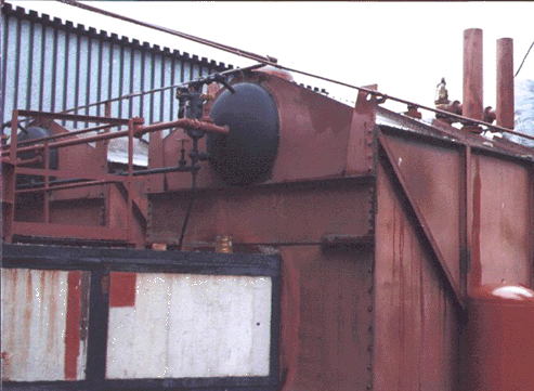 |
Combusted gas enters the boilers via light colored ductwork from the secondary combustion chamber of Olivine type incinerator. Both boilers rely on waste heat only. There are no backup burners used. Each boiler is equipped with two safety valves. |
Turbo generator
Turbo generator used in this installation is old General Electric
unit built in 1916. Turbo generator was completely reconditioned by Dynamic
Energy Corp. All parts were checked and remachined when required.
Turbine has three stages, two velocity compounded Curtis stages
and one low pressure impulse type stage. Turbine is capable of 1,500 horse
power and is direct coupled to 1 Mw electric alternator. Turbine has mechanical
speed governor actuated by fly weights. The governor motion is amplified
by hydraulic cylinder which then drives the main steam control valve in
turbine's inlet in order to maintain 3600 revolutions per minute.
Electric output from the alternator is up to 1,200 kw at 460 volts
60 Hz. Alternator excitation is controlled by a belt driven DC generator
and the alternator voltage output is controlled by electronic voltage regulator.
Voltage range can be set anywhere from 440 volts to 480 volts.
|
Direct drive 1 Mw turbo generator set Exciter is belt driven dynamo (on the right). This unit was built in 1916, was relocated twice, and it was completely reconditioned for this job. |
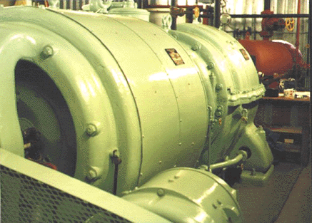 |
Control Panel
The control panel for the above generator was built in 1960
and again it was rebuilt by Dynamic Energy Corp. for this installation.
The power plant has an independent control panels separate from incinerator
control panels. There are two control panels. One is totally devoted to
alternator monitoring and protection. The other panel is used to control
entire power house equipment and switch gear.
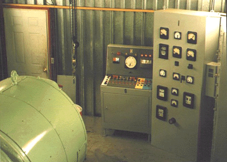 |
We used most of the original equipment built in 1960. Some additional modern electronic protective relays were added to comply with utility grade requirements. Also, the original mechanical voltage regulator was removed and replaced with an electronic voltage regulator. |
Switch gear
We used old Allis Chalmers 1,600 Amps breakers to connect or interrupt the electric power from alternator. These are motor operated breakers for closing. Breaker tripping mechanism is actuated by DC electromagnet which is powered with DC current from large electrolytic capacitor. This ensures that there is always enough power to trip the breaker when all other power fails, as in the case of short circuit. Electronic protection relays are used to activate the breaker trip mechanism when fault conditions get out of specified limit. Two breakers are used. One breaker feeds electric panels for power distribution in the incinerator plant and the second breaker can connect electric power to utility grid.
Deaerator and Boiler Water Feed
Spray type deaerator is used. ( Deaerator is a device to remove dissolved
oxygen from boiler feed water ) . Condensed water from the surface condenser
is pumped via spray nozzles into a low pressure vessel where the water
is contacted with steam. Steam heats the water to 220 - 250 degrees F.
Over 99% of dissolved oxygen is driven off once the boiling point of water
is reached. The residual oxygen is scavenged by Sodium Sulfite chemical.
The removal of oxygen from boiler feed water is of the out most importance
because the dissolved oxygen in feed water can damage the boiler by pitting,
leading to boiler destruction.
Deaerated water is pressurized by electrically driven multistage
pump and is ready to be injected into boiler on demand. The pressurized
pump outlet piping has a bypass valve to return water back to pump inlet
when boiler water level controller demands less water. This system
assures the constant flow of water trough the pump, an essential requirement
for a proper performance of multistage centrifugal pump. The system has
one standby back up pump which starts automatically when boiler water level
drops below certain level.
Water bypass valve is pneumatically operated to on or off state.
The signal to operate this pneumatic bypass valve is taken from McDonnell-Miller
boiler controller There is also back up from two electronic water level
controllers.
The overall system has high degree of reliability and the maintenance
cost was less than $100.00 in years of operation.
|
On the left are two multistage boiler feed pumps. The pneumatically boosted steam bypass valve is located in between large black pipe and the huge 36" turbine exhaust pipe. This valve is holding steady 160 psi boiler pressure. Steam driven air ejector (vacuum pump) can be partially seen on the right. |
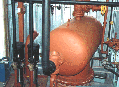 |
Condenser and Cooling Tower
Condensing steam power plants have better thermal efficiency, hence
if steam is not required for any process it is desirable to condense steam
back into water and recycle the water back into boiler. Usually a surface
condenser is used to condense the steam exhausted from turbine. Steam condensing
must take place under deep vacuum condition. The reason for it is two fold.
One, if the air is present in the condenser it prevents the steam contact
with condenser tubes because the air is already occupying the space, hence
the surface condenser will not operate properly if there is air in it.
Secondly, if the steam is expanded, via turbine, into deep vacuum
more power is extracted from each pound of steam. It is desirable to hold
the vacuum at minimum of 28.5 inches of mercury. If there is enough cooling
water of low temperature it is easy to reach 29.5 inches vacuum. The theoretical
30 inches of vacuum is impossible to reach, therefore, 29.5 inches is very
good vacuum. Steam driven two stage air ejector is constantly operated
to keep ahead of infiltrating air leaking into the condenser system.
Surface condenser ejects a massive amount of low grade heat, therefore,
a lot of cooling water is required. The steam temperature entering the
condenser under 29 inches of vacuum is about 100 degrees F, however, the
enthalpy ( heat content ) of steam is still over 1,000 BTU per pound, hence
you can see that a huge amount of heat must be ejected into cooling water.
For example: If the turbine uses 20,000 pounds of steam per 1Mw / per hour
( modern and large turbines use less steam, some below 10,000 lb per 1Mw/h
), it means that over 20 million BTU of heat energy must be ejected into
cooling water.
The most common method of providing cooling water for condenser
is to recirculate cooling water via cooling tower where the recirculating
water is cooled by evaporation and air contact. In our installation we
use a refrigeration type cooling tower. This cooling tower is of compact
round design with rotary water distribution over the evaporative surface.
Motor driven cooling fan of 10 feet diameter is used to provide air movement
through the cooling tower. Water recirculation is at 1,400 gallons per
minute. The power consumption for air fan and recirculation pump is only
15 Hp. This is very efficient, due to low height difference between condenser
and cooling tower discharge, therefore, the pump doesn't have to lift water
too high, resulting in power savings.
|
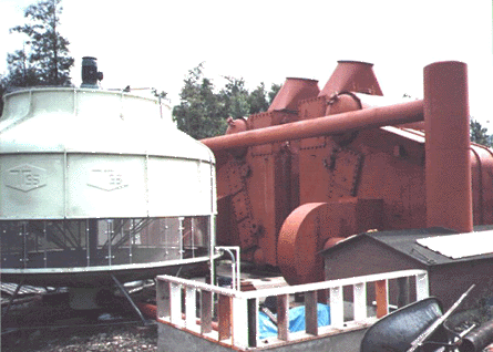
Refrigeration type cooling tower. Water is pumped via underground 8" pipe and enters through the centre into midd section of cooling tower where water is sprayed out of rotating sprinkler onto cooling tower packing. Water is passing counter current to rising air. Cooled water is then recirculated through condenser. |
 |
Chemical Water Treatment
Every steam power plant requires some chemical water treatment for
uninterrupted reliable operation. In our installation, we provided an inexpensive
yet very effective water treatment system. Water softener is the first
most important device in water treatment. Savings in chemicals will far
outweigh the cost of water softener. The softened water is further
treated with three chemicals. Sodium Sulfide is used for residual oxygen
scavenging. Sodium Hydroxide is used for PH ( alkalinity ) adjustment,
and Phosphate is used as an anticorrosion agent to protect piping in condensate
system.
Cooling tower uses two chemicals. One is anti scaling agent to prevent
lime scale build up in recirculating system. The other chemical is anti
algae agent. Without this chemical there is a problem of algae slime build
up on all parts of cooling tower.
Chemical dosage is monitored with chemical analysis because too
much dosage would waste the chemicals and too little could result in some
problem.
Conclusion
The above described power plant was designed and built by Dynamic
Energy Corp. The total cost of purchasing used equipment,
reconditioning and direct labor in construction was about US$ 150,000.00
and it took more than one year to finish all equipment reconditioning and
construction.
The operation was trouble free so far, maintenance is mainly consisting
of labor cost for chemical monitoring and preventive maintenance. The operating
cost is low and it consist of annual boiler inspection and fees, less than
$1,000 in chemicals per year and boiler safety valve reinspection and retesting
in certified shop.
Operation of power plant is completely automatic, therefore,
it doesn't require additional personnel to operate it. The incinerator
plant supervisor and incinerator operators are running this power
plant.
Company
Dynamic Energy was incorporated in Delaware in 1990, and this company
is also registered in Washington State. The company was formed specifically
to build and operate the steam power plant at Olivine Corporation in Bellingham,
WA
The company was involved in managing the construction operations
and then managing the plant operations.
Now the company is in the process to expand it's operations into
manufacturing of various metal and electronic products in the Philippines
under the name Unity Machineworks Inc.
|
The Dynamic Energy Corp. is available for hire anywhere in the world for consulting, designing, building or operating your steam power plant. Our expertise is in Municipal Solid Waste Incineration and wood waste incineration with the addition of power plant design and an environmental anti pollution design. |
People involved in Power Plant construction / operation
Listing starts from the beginning of power plant construction for all people who participated in administration, construction work and operation. Two companies were involved.
Office Administration ( Olivine Corporation) Corky
Smith Sr., Corky Smith Jr., Mae Smith,
Tom Dutcher, Katleen Perkins, Rolf Nilsen
Job Design and Supervision (Dynamic Energy Corp.) - Frank Kandrnal
Foreman - Jim Prince & Riley Cunningham
Construction Labor - Tim Tracy, Doug
Corning, Jerry Hansen, Antonin Gajdosik Sr.,
Abe, Paul Wright, Antonin Gajdosik Jr., Vic Hubacek, Peter
Carlich
Purchasing - Pamela Clayton, Tanya Kandrnal
Incinerator/Power Plant Operators - Tom
Creel, Bradley Mumm, Larry Thompson,
Modesto (Nino) Silva, Robert Davies, Don Burton,
Bob Johnson, Luis Gierke, Randy Flather
Plant Operations Management ( from 1992 to 1995) - Frank Kandrnal
Plant Operations Management ( from 1996 ) - Jim Prince
Machine Maintenance - Dave Devaney
Water Treatment Monitoring - Tanya Kandrnal, Marwin Woods
|
|